Powerline LiDAR deliverables: what a utility actually receives
A powerline survey is flown for a small number of answers: where the conductors are, how far they hang from the ground and from the trees, and where the structures that hold them stand. The classified point cloud is how those answers are stored, but it is rarely what the utility's engineer opens first. What they receive is a package, and each item in it depends on the one before. This piece lays the package out in the order it is built, with the class codes and the obligations that shape it.
Why the survey exists at all
In North America, transmission owners manage vegetation under NERC's FAC-003 standard. Its stated purpose is to prevent vegetation-related outages that could cascade, and its first requirement is to keep vegetation out of a minimum clearance distance around each applicable line, for four kinds of encroachment: an observed encroachment into the clearance distance, a fall-in from inside the right of way, vegetation blowing together with a line, and grow-in [1]. The standard also requires an inspection of every applicable line at least once a calendar year, with no more than eighteen months between inspections of the same right of way [1]. Airborne LiDAR is the usual way to make those inspections measurable, and every deliverable below exists to serve one of those clauses.
1. The classified point cloud
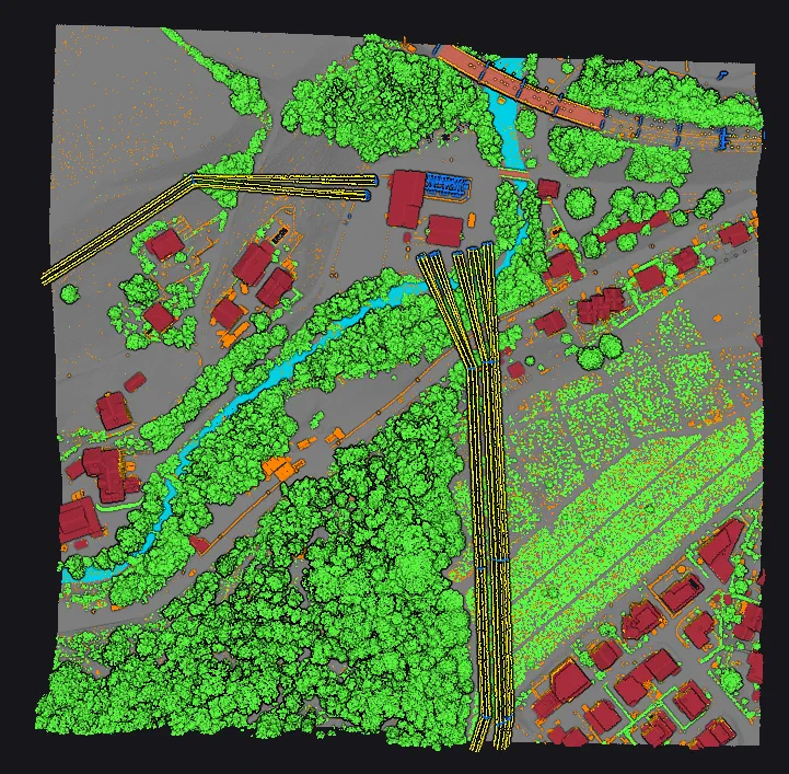
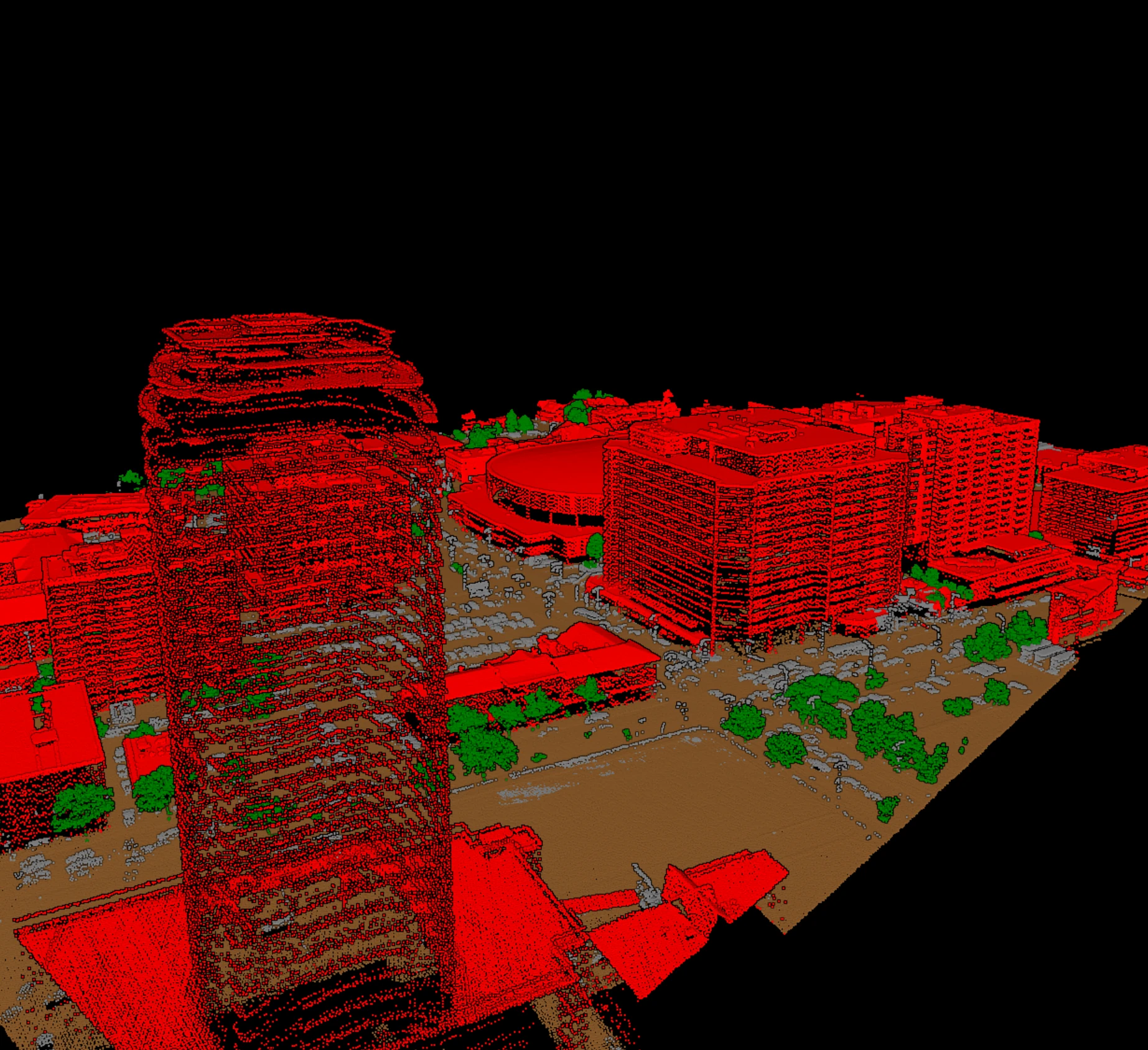
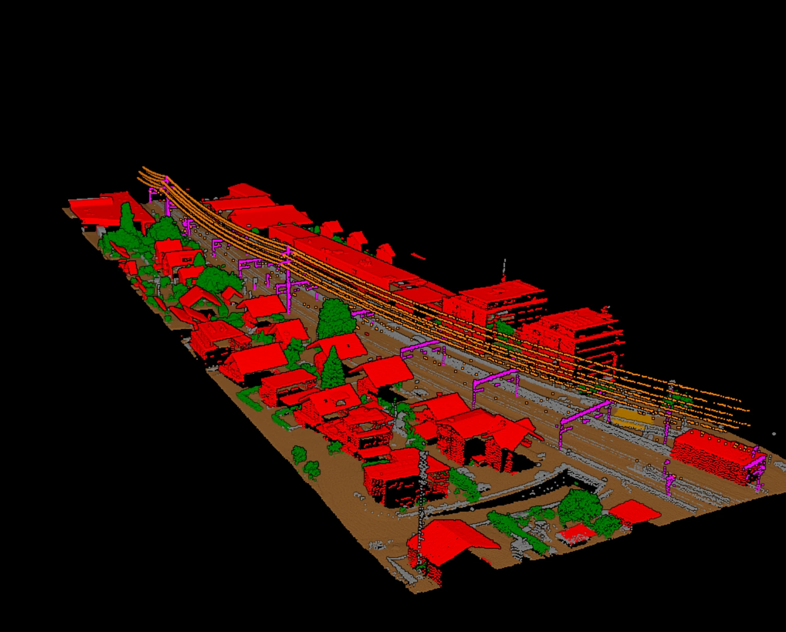
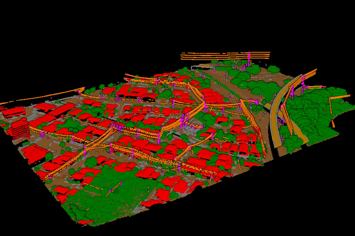
Everything starts with a LAS or LAZ block in which the corridor classes are set. The LAS specification reserves standard codes for exactly these objects: 13 for guard or shield wires, 14 for conductors, 15 for transmission towers, and 16 for wire-structure connectors such as insulators, alongside 2 for ground, 3 to 5 for vegetation, 6 for buildings, and 7 and 18 for low and high noise [2]. Those codes exist only in point data record formats 6 to 10, so a corridor file has to be written in a modern format; the legacy formats have no legal place for a wire [2]. A block with these classes set, and with the ground clean underneath the line, is the foundation deliverable. Our note on classifying utility corridors covers why the wire classes are the hard ones.
2. Conductor and structure vectors
A classified conductor is still a ribbon of points. The engineer's model needs a line: one polyline per conductor, per span, fitted through the class 14 points, plus a point or a small footprint per structure taken from the class 15 points, with an identifier that carries from one deliverable to the next. Fitting the line is extraction, not classification, and it is where a dropped span or a merged pair of conductors in the classification becomes a missing or wrong vector. That is why the classified block is reviewed span by span before the vectors are cut.
3. Spans, attachment points, and the ground profile
Between each pair of structures, a span record ties the conductor vectors to their attachment points and to the ground beneath them. This is where the modelling software takes over. The public sample survey specification published by the makers of PLS-CADD, the software most transmission engineers model in, shows what that hand-off expects: LAS or LAZ files, a minimum point density it states as fifteen points per square metre, up to four returns per pulse rather than first-or-last-only systems, and feature-coded coordinates interpreted from the LiDAR rather than raw point clouds, using the software's own feature codes for ground, roads, and structures rather than ASPRS classes [3]. The same document is explicit that the ground must be dense enough to render as a triangulated surface in the model [3]. Those are one vendor's sample terms, not a standard, but they are typical of what a utility writes into a request for proposals.
4. Clearance zones and encroachment reports
The last derived deliverable is the one the vegetation manager reads. Around each conductor, at the operating conditions the engineer specifies, a clearance envelope is built and every vegetation point inside it is reported: its location, its height, its distance to the nearest conductor, and the span it threatens. FAC-003 defines the minimum distance from a calculation in its own tables rather than from a survey, and the modelling software predicts where the wire will be under wind, ice, and temperature [1], [4]. What the survey supplies is the vegetation and the as-flown wire; what the model supplies is the wire under load. A grow-in check compares the two over time, which is why span and structure identifiers have to be stable from one year's flight to the next.
The package at a glance
| Deliverable | Built from | Usual formats |
|---|---|---|
| Classified point cloud | The survey, with classes 2 to 7, 13 to 16, and 18 set | LAS or LAZ, record format 6 or higher |
| Conductor vectors | Class 14 points, one line per conductor per span | Shapefile, GeoJSON, DXF, or the modelling software's own format |
| Structure points | Class 15 points, one record per tower or pole | Shapefile or CSV with identifiers |
| Ground profile | Class 2 points along and beside the line | Triangulated surface or coded ground points |
| Span table | Structures paired along the line, with attachment points | CSV or the modelling software's own format |
| Encroachment report | Vegetation points inside the clearance envelope | Spreadsheet, KML, or a map service |
Acceptance checks the utility will run
- Every span present end to end in the classified cloud, with no conductor merged into its neighbour.
- Every structure complete from ground to top, with the same identifier as last year's flight where one exists.
- Ground dense and clean beneath the line, because the clearance is measured to it.
- Point density and return count at or above what the specification names, checked on the delivered tiles rather than the flight plan.
- Coordinate system records and point flags preserved through classification, so the vectors land on the utility's base map.
Vecten's VUtilities module classifies wires, poles and towers, and connectors alongside ground, vegetation, and buildings, and writes the block with the standard codes and review layers for the span-by-span check. Vecten Desktop runs it on your own workstation; Vecten Cloud runs the same models in the browser.
Frequently asked questions
- Which LAS classes are used for powerlines?
- Code 13 for guard or shield wires, 14 for conductors, 15 for transmission towers, and 16 for wire-structure connectors such as insulators. They are defined for point data record formats 6 to 10 only.
- Does the survey measure the clearance distance?
- It measures the as-flown geometry. The minimum clearance itself comes from the standard's tables, and the wire position under wind, ice, and temperature comes from the engineer's model. The survey supplies the vegetation and the structures that model needs.
- What point density does a corridor survey need?
- Denser than general mapping. One public sample specification names fifteen points per square metre and at least four returns per pulse; the contract you sign will state its own figure, and it should be checked on the delivered tiles.
- Can the classified cloud go straight into PLS-CADD?
- Not as a point cloud. The published sample specification asks for feature-coded coordinates interpreted from the LiDAR, using the software's own codes, so an extraction step sits between classification and the model.
References
- [1] NERC, *FAC-003-5 – Transmission Vegetation Management*, North American Electric Reliability Corporation. nerc.com
- [2] ASPRS, *LAS Specification 1.4 – R16*, The American Society for Photogrammetry & Remote Sensing, LAS Working Group, 2025. github.com/ASPRSorg/LAS
- [3] Power Line Systems, *Sample survey specification for PLS-CADD*. powerlinesystems.com
- [4] Power Line Systems, *Transmission & distribution line vegetation management in PLS-CADD*, technical note, 2020. powline.com